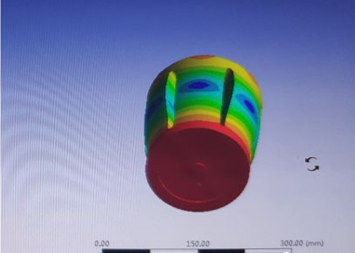
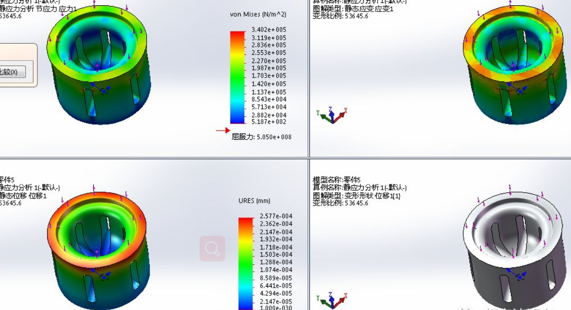
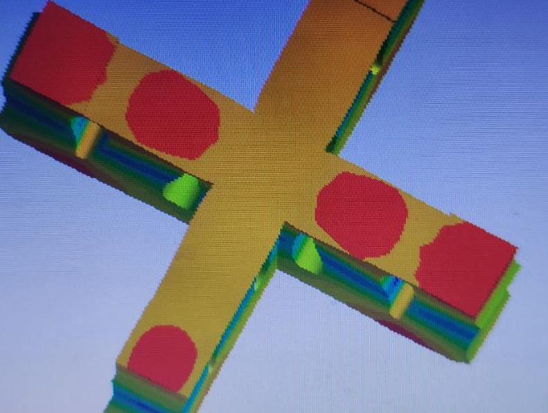
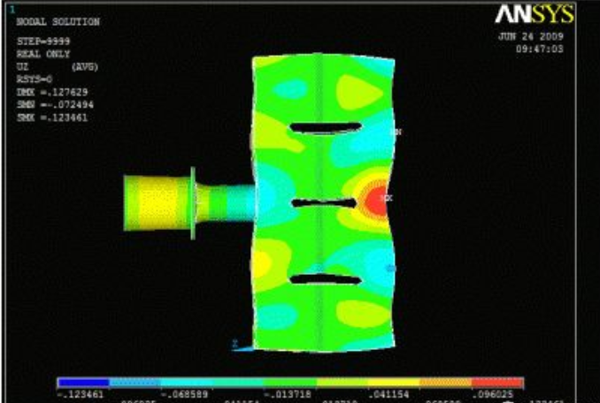
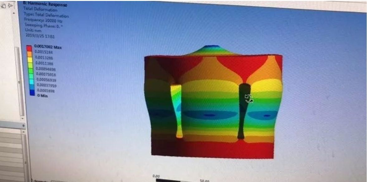
Different welding horns are required for different welding objects, no matter near field welding or transmission welding, only half wave length ultrasonic horns can achieve the maximum amplitude of the welding end face. Ultrasonic horns , available with and without amplitude. Ultrasonic plastic welding machines make ultrasonic horns using ultrasonic principles.
Ultrasonic mold design is not as simple as its appearance, when using a improperly processed or untuned welding horn, it will cause expensive losses to your production – it will destroy the welding effect, or even more serious will directly lead to the damage of the transducer or generator. Ultrasonic mold design requires a lot of specialized knowledge and skills – how to ensure that the welding horn can work economically? How to ensure that the welding mold can effectively transfer the mechanical vibration converted by the transducer to the workpiece, our engineers have fully considered every link.
Welding horn is a very important part in ultrasonic plastic welding equipment, and its design is directly related to the welding quality. The strip welding joint is divided into several equal elements by reasonable slotting, and each element can be treated as compound stepped horn. The frequency equation of the welding joint element is obtained by transfer matrix method, which provides a theoretical basis for the design of the strip slotting joint.
The experimental results show that the measured frequency and the designed frequency are good for the strip welding joint designed by this equation. This design method has obvious physical significance, simple calculation and is very suitable for engineering design. In addition, the influence of slot number, slot width and slot length on welding head size can be conveniently calculated by using this method, which also provides a theoretical basis for the optimization design of welding horn.
Ultrasonic plastic welding equipment is generally composed of ultrasonic power supply, ultrasonic vibration system and pressure mechanism, and the ultrasonic vibration system is composed of ultrasonic transducer, booster and welding horn. Ultrasonic transducer and horn are generally designed to resonate at a certain frequency, and do not need to change the different welding parts, and the welding horn needs to be specially designed according to the shape of the welding parts. The good or bad of its design is directly related to the welding quality, so it is a very important part in the welding equipment.
For large welding parts, they need the large size welding horn, and its size is sometimes close to or more than one longitudinal wave wavelength, then the welding horn will produce serious transverse vibration, resulting in uneven displacement distribution of its radiation surface. In order to obtain satisfactory amplitude distribution, some methods, such as slotting, slit opening, adding additional elastomer and secondary design, have been put forward.
Vibration is controlled, among which slotting is the most commonly used method to simulate transverse vibration of welding joints . Because of the complexity of the shape, it is difficult to get a strict analytical solution for the slotted welding joints, so numerical calculation methods such as Ansys method are more often used to analyze these problems. According to previous studies, numerical method is more suitable for the later optimization design of welding joints, and has no advantage in estimating the size and frequency of welding joints at the initial design stage. In order to ensure better optimization results, it is very important to estimate the structure size that can roughly meet the design requirements, so it is of practical significance to study the design theory of large-size welding joints with grooving configuration.
Split groove after strip welding head vibration analysis, the welding head can be divided into the end unit body and middle unit cell, using the apparent elasticity method and the method of equivalent transmission lines, the length of the four different units are given respectively and the direction of the high degree of frequency equation, the frequency equation can be used to design a long bar welding head, but the design process is complicated, The selection of some parameters depends on experience and is not convenient for engineering application. In this paper, the strip welding joint is divided into several equal elements by reasonable slotting, and the frequency equation of the welding joint element is obtained by transfer matrix method, which provides a theoretical basis for the design of the strip welding joint. The design has simple theoretical calculation and obvious physical significance, which provides a simple and feasible method for the engineering design of strip welding joint.
Post time: Mar-16-2022

